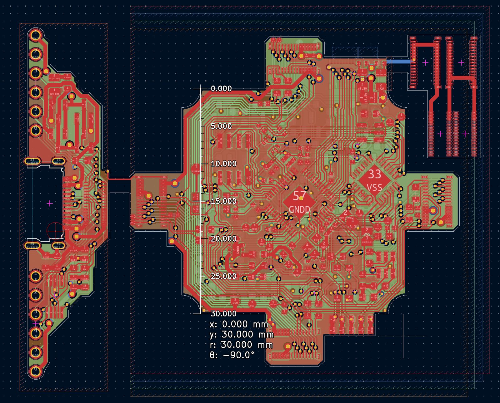
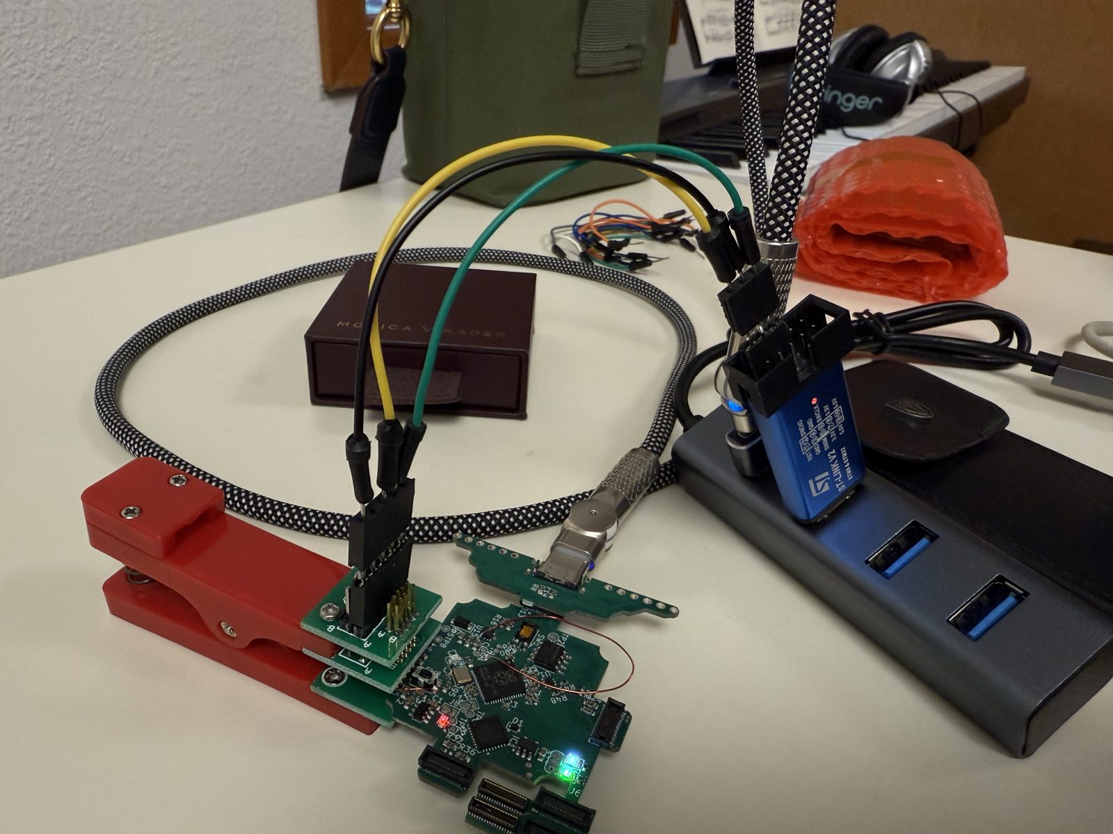
4 stereo inputs to 4 outputs, tileable, first 4-layer board
Overview
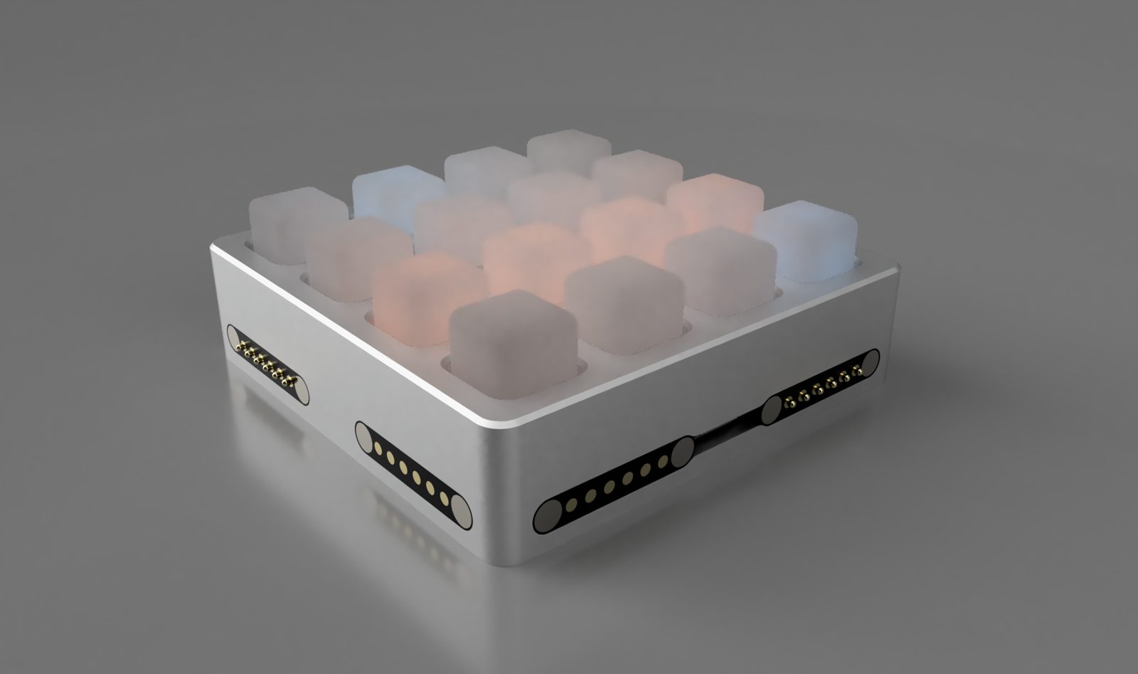
This is a project I worked on the summer before going to stanford. It routes 4 stereo audio channels to 4 outputs, and is tileable.
Say we label columns like 1 2 3 4 and rows like A B C D. Then pushing A1 routes input A to output 1.
Push a button, route that row’s input to that column’s output
1
2
3
4
A
A1
A2
A3
A4
B
B1
B2
B3
B4
C
C1
C2
C3
C4
D
D1
D2
D3
D4
Every row is one continuous bus: it starts at the input jack on the left and is tied straight through to the right edge. Every column is the same top to bottom. A button just bridges its row onto its column, which is what makes the thing tileable.
One tile. Row A is a single wire from input A to A end, and signal can pass either way along it. Each column is likewise one wire from its top to its output. A button bridges its row onto its column.One tile. Row A is a single wire from input A to A end, and signal can pass either way along it. Each column is likewise one wire from its top to its output. A button bridges its row onto its column.
Put two tiles next to each other and the row ends of the first feed the row starts of the second. Call the second tile’s buttons and jacks primes: A′, 2′. Pushing A2′ routes input A to output 2′, all the way across the first tile.
Two tiles side by side: tile 1’s row ends feed tile 2’s row starts, so row A continues as A′. Pushing A2′ puts input A on the whole of row A and the whole of column 2′, so it appears at output 2′ (and at A′ end and the top of 2′).Two tiles side by side: tile 1’s row ends feed tile 2’s row starts, so row A continues as A′. Pushing A2′ puts input A on the whole of row A and the whole of column 2′, so it appears at output 2′ (and at A′ end and the top of 2′).
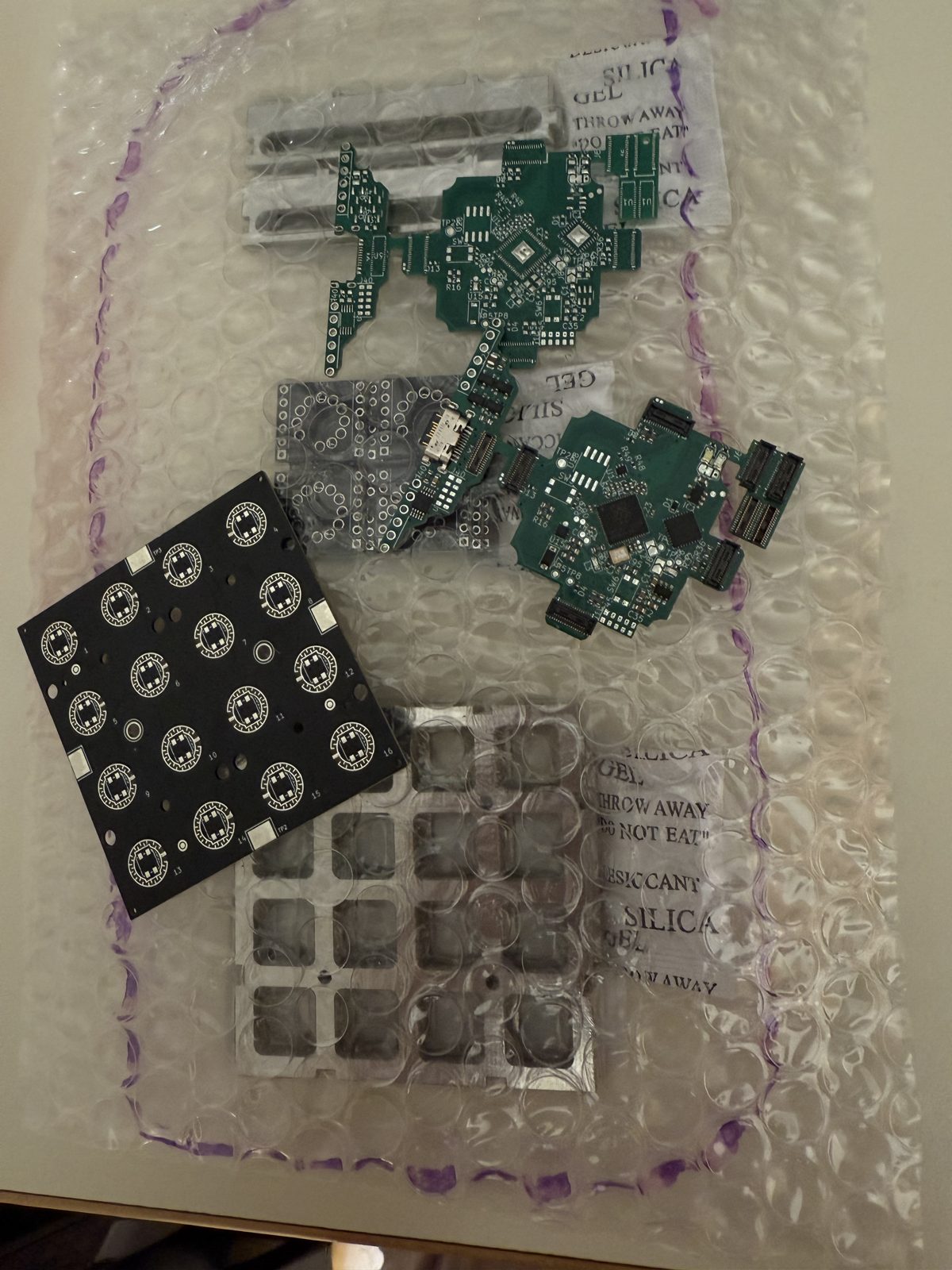
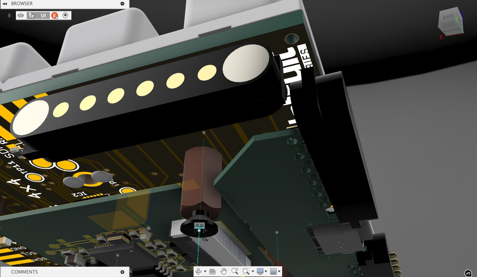
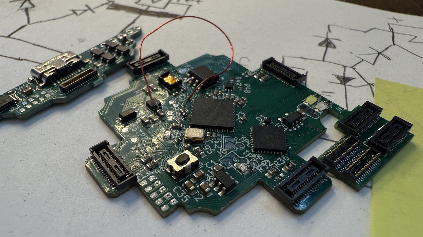
Nati Grinkrug made the sweet enclosure model and render back in the day before vibecad. This was my first 4 layer pcb. Quite a complicated mech.